News
When a CNC milling machine starts chattering on mold steel, operators often check the tool first. In many cases, however, the real culprit is poorly selected cutting conditions. Cutting conditions determine tool life, surface finish, and cycle time, so understanding how to set them correctly matters more than simply cranking up the spindle speed.
Cutting conditions in milling are built from a small set of variables that interact with each other. The most important parameters are cutting speed, feed per tooth, and depth of cut. Changing one affects the others, which is why the first step is to know what each parameter means and how it influences the process.
Quick observation: A machining setup is only as good as its parameter combination. A perfectly sharp tool can fail in seconds if the cutting speed is too high for the material.
| Parameter | Symbol | Definition | Typical Unit |
|---|---|---|---|
| Cutting speed | v_c | Surface speed of the tool edge through the material | m/min |
| Spindle speed | n | Rotation speed of the spindle | rpm |
| Feed per tooth | f_z | Feed rate divided by the number of cutting teeth | mm/tooth |
| Table feed | v_f | Speed at which the table moves | mm/min |
| Axial depth of cut | a_p | Depth of cut along the spindle axis | mm |
| Radial depth of cut | a_e | Width of cut perpendicular to the spindle axis | mm |
| Metal removal rate | Q | Volume of material removed per minute | cm³/min |
To avoid guesswork when selecting a tool for a new job, refer to a milling cutter selection guide that walks through geometry, materials, and parameters step by step.
Conclusion first: cutting speed directly controls tool wear and heat generation. For most indexable milling tools, you should start from the manufacturer recommendation for the workpiece material and adjust downward for tough alloys or older machines.
The relationship between cutting speed and spindle speed is simple:
v_c = (3.14159 * D * n) / 1000
D is the cutter diameter in millimeters and n is the spindle speed in rpm. An 80 mm face mill running at 1200 rpm gives a cutting speed of about 302 m/min. If the material is P20 mold steel, this is a reasonable starting point. For hardened steel above 40 HRC, you would reduce v_c to around 120 to 180 m/min.
Reference cutting speed ranges for common materials:
When cutting speed is too high, the cutting edge zones experience rapid cratering and thermal cracking. When it is too low, the tool rubs instead of cutting, producing poor surface finish and higher cutting forces.
The tool body itself matters as well. A well-designed CNC face milling cutter with AN inserts can handle high cutting speeds while maintaining stable chip flow, which helps when you push toward the upper limit of the recommended range.
 CFM90AN Face Milling Cutter for Versatile Roughing and FinishingThis face milling cutter with AN inserts offers stable chip flow at high cutting speeds, making it suitable for roughing and finishing steel, stainless steel, superalloys, and cast iron.View Product →
Conclusion first: feed per tooth is the primary driver of chip thickness, and chip thickness determines both tool load and surface quality. The formula is simple: f_z = v_f / (n * z), where z is the number of effective teeth.
For roughing operations, machinists typically run higher feed per tooth to maximize metal removal. For finishing, a lower f_z produces thinner chips and better surface texture. A common approach is to set f_z between 0.08 and 0.15 mm/tooth for finishing on face milling, and between 0.15 and 0.30 mm/tooth for roughing.
The relationship between feed rate and productivity becomes clear when you calculate table feed. A 40 mm face mill with 5 inserts running at 1500 rpm and f_z = 0.20 mm/tooth requires a table feed of 1500 mm/min. If the machine cannot reach that speed, the feed per tooth must be lowered.
Practical risk: Increasing feed per tooth beyond the tool edge capability can cause insert breakage or edge chipping, especially on hard materials. Keep an eye on chip shape and cutting sound.
For applications targeting high material removal, a high feed milling cutter series allows elevated feed rates at reduced radial engagement, which helps protect the tool while improving productivity.
 CFMSX-13 High Feed Face Milling Cutter for Reduced Radial EngagementDesigned for high material removal with reduced radial engagement, this cutter decomposes radial forces to enable elevated feed rates, ideal for long-overhang machine tools and mold roughing.View Product →
Conclusion first: axial depth of cut controls how much material each tooth must remove along the spindle axis, while radial depth of cut determines the arc of engagement. Together they define the actual load on the cutter body and the required power.
In slotting, the cutter engages with a radial depth equal to the full cutter diameter. This demands maximum power and creates the worst chip evacuation condition. In face milling, radial engagement is often 50 to 70 percent of the cutter diameter, which reduces the impact on the tool and allows higher feed rates.
A practical rule for solid carbide end mills is to keep the axial depth of cut below 1.5 times the cutter diameter in roughing, and much smaller for finishing. Deep cuts should be broken into multiple passes, because excessive depth can lead to chatter, deflection, and poor dimensional accuracy.
If a spindle motor overload occurs, reduce the axial depth first, then check radial depth. Reducing radial engagement by half can cut power consumption by approximately 30 to 40 percent while preserving the same axial depth.
Choosing the right end mill for depth-sensitive jobs matters. A solid carbide end mill with a rigid shank design performs well in deep slotting and profile milling where the axial load is significant.
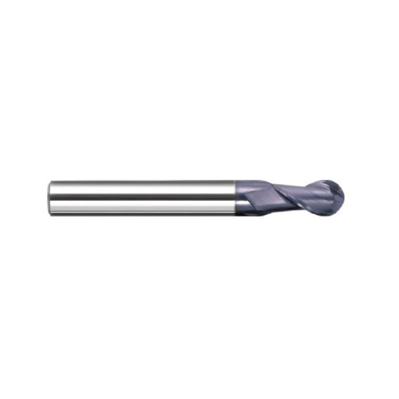 CHB2 Solid Carbide End Mill for Deep Slotting and ProfilingA solid carbide end mill with a rigid shank, available in two- and four-flute flat and ball end designs, suited for deep slotting and profile milling in hardened steel and cast iron.View Product →
Conclusion first: climb milling is the standard choice for most CNC operations because it improves surface finish and prolongs tool life. In climb milling, the tool enters the workpiece at the top and the chip starts thick, then gets thinner. In conventional milling, the chip starts thin and ends thick.
Climb milling creates a downward cutting force that presses the workpiece against the table, reducing vibration. It also produces a burnishing effect on the finished surface. However, on older machines with significant backlash, climb milling can cause the table to surge. In that case, conventional milling is safer but produces a rougher surface.
When testing new cutting conditions, pay attention to chip burning, tool-edge discoloration, machining sound, and the feel of the spindle load. These signals help confirm parameters before committing to a large production batch.
Cutting conditions are the set of process parameters used to guide a milling cutter through a workpiece, mainly including cutting speed, feed rate, and depth of cut. They directly affect machining efficiency, surface quality, and tool life.
High cutting speed generates excessive heat at the cutting edge, which accelerates crater wear, thermal cracking, and flank wear. It can also cause a polished but heat-damaged surface or even tool failure within minutes.
Observe the chip form and color, listen for chatter, and inspect the tool edge under magnification. Light-colored, consistent chips and a steady cutting sound usually indicate reasonable parameters. Blue chips or burned tool edges suggest the conditions are too aggressive.
Yes. Coated carbide tools can withstand higher cutting speeds than uncoated tools. Coatings such as TiAlN reduce friction and thermal stress, allowing you to increase cutting speed and feed rate while preserving tool life. Always check the coating recommendation for the given workpiece material.
For more practical help on choosing cutters, see the end milling cutter selection guide that covers common machining scenarios and parameter recommendations.
In practice, cutting conditions are never static. You adjust them based on machine rigidity, workpiece material, tool condition, and the specific quality target. Start with recommended values, monitor the process, and make small changes. The result is a milling process that runs quietly, produces consistent chips, and leaves the tool intact for the next job.


ChaiTools is specializing in the research and development, design, production, sales and technical support of high-end CNC tools.
 +86-571-83502022
 +86-18867120330
+86-18857186736
+86-13615816276
 +86-571-82529638
 11 Floor of No.2 Wanyushuzhigu Building, Dongrui 4# road, Xintang Street, Xiaoshan District, Hangzhou City, Zhejiang Province, China. POST CODE 311201
Copyright © 2022 Hangzhou Chai Cutting Tools Co., Ltd. All Rights Reserved. CNC Turning Tool Holders Manufacturers


 English
 Deutsch
 русский
 Español
 中文简体